Dual coil technology is fast becoming the new “buzz” word within the diesel common rail (CR) aftermarket. Due to its advanced pressure and injection control techniques, along with twin channel injector firing protocols, it initially presented a challenge for Hartridge when developing a test solution for the Sabre CRi Expert; but as we have said in previous blogs we will take the path to achieve best results even if this isn’t the easy path!
Bosch has a dual coil injector in the market today, known as CRIN4.2. This contains an electronically controlled pressure amplification module known as an intensifier, and a separate electronically controlled nozzle control valve.
Interestingly, this technology is not just limited to Bosch. We have been well informed that other leading fuel injection (FI) manufacturers are developing similar dual coil technology in order to meet future emissions requirements beyond Euro 6.
Therefore it was essential that we provide the best solution possible for this need in the market.
What is a Dual Coil Injector?
The Bosch CRIN4.2 injector is the first of its kind to utilise two solenoid valves. One controls pressure, whilst the other controls the injection event.
In the Bosch CRIN 4.2 injector pressure control is achieved by a pressure amplification module; this is also commonly referred to as an ‘intensifier system’. Its purpose is to increase the system rail pressure at a typical ratio of 2:1. The intensifier system is housed inside the injector body and typically comprises of an intensifier piston, oil control valve and dedicated coil.
The benefits of this are that the maximum system rail pressure is significantly lower, typically in the region of 800-1200bar, which puts less strain on the CR pump and external high pressure components, which directly improves the durability and reliability of the CR system.
Depending on the engine running conditions the intensifier system will be actuated for a controlled period of time to amplify the injection pressure based on the pressure vs. flow maps which are predefined within the vehicle ECU.
The injection event is activated by a separate dedicated coil and valve assembly which is very similar to any other CR injector design. The main purpose of this valve is to inject fuel at the correct time and for the correct time period, again, this mirrors the functionality of any other CR injector in the market today.
In fact, until we look further into how the dual coil system works, it looks unnecessarily complicated and unremarkable.
Bosch CRIN4.2 R&D at Hartridge
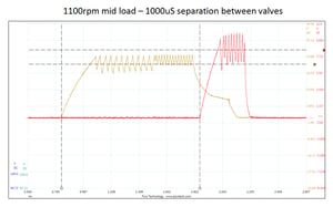
During our extensive on-vehicle R&D testing, shown in our video, it was identified that the intensifier and nozzle control valves were in fact not actuated by the vehicle ECU as we initially envisaged.
This surprised us; we initially assumed that the intensifier system would be actuated before the nozzle control valve to amplify the pressure before the start of injection and then remain actuated during the injection event to maintain pressure amplification during the injection event.
However, what we identified was that the actuation logic of both the intensifier system and nozzle control valves was completely dependent upon the engine speed and load conditions.
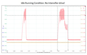
Whereas in some circumstances the intensifier system would be actuated after the nozzle control valve and in others the intensifier system would not be actuated at all!
So what benefit does this control strategy to offer?

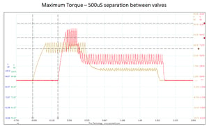
What we identified is that the intensifier system actually has two purposes. The obvious one is to amplify the system rail pressure to achieve a high injection pressure. However, the other purpose, which is actually more significant, is that the rate of injection during the injection event can be controlled by changing the actuation relationship between the intensifier and nozzle valves. This is directly controlled by the vehicle ECU depending on the actual and requested loads from the vehicle driver and is fundamental to how the injector is designed to perform.
For example, under testing we found that actuating the intensifier system 500uS before the nozzle valve provides a very sharp and fast injection rate. This would remain constant if the intensifier valve was left actuated while the nozzle is open.

If then the intensifier system is actuated 500uS after the nozzle valve then the injection rate stays at the system rail pressure during initial nozzle opening but increases significantly during the injection event period, depending on the length of time the intensifier valve is energised for.

For the idle, fast idle, low load engine conditions only the nozzle valve is actuated as the pressure generated from the CR pump is perfectly adequate for these running conditions. However, when aggressively accelerating or demanding high load particularly at low engine speeds, the intensifier system amplifies the injection pressure and completely changes the injection profile.
This is where the CRIN4.2 CR injector is unique and we have found that the number of injection profiles used depending on the actuation relationship is virtually limitless.
How do I correctly test these injectors?
There is one disadvantage to the CRIN4.2 injector and that is its inability to determine the actual injection pressure within the intensifier system as it is activated.
As mentioned, depending on the engine running conditions the intensifier system will be actuated for a controlled period of time to amplify the injection pressure based on the pressure vs. flow maps which are predefined within the vehicle ECU.
Discover: Our blog on our common rail coding mission
Since there is no feasible method to measure the injection pressure within the injector itself, the vehicle ECU relies on a predefined number of maps to theoretically calculate the injection pressure based on the intensifier logic and therefore the system operates in an open loop state.
The negative consequence of this is that the predefined maps and calculations are only viable if the intensifier system is operating in exactly “as new” condition.
We see a number of customers claiming to have the technical capability to fully test these injectors by just actuating the nozzle control valve, as per a standard single coil CR injector. This test method does provide a basic function check of the nozzle and control valve as isolated components but certainly doesn’t diagnose the entire injector as it fails to check the intensifier functionality.
This message is reinforced by reports of workshops experiencing high failure rates when fitting these “tested” injectors back into the engine; therefore it is clear that testing only the nozzle functionality is insufficient.
Watch our video trailer for all the latest launches coming for the Sabre CRi Series!
The only way to correctly test the CRIN4.2 CR injector is to develop the ability to actuate both the intensifier and nozzle control valve simultaneously. This is only possible if the test platform has twin driver channels that can be actuated and controlled independently. We are not just referring to independent pulse width control, but additionally developing independent voltage and current profiles for both valves. Ultimately therefore, the test platform needs to be extremely flexible.
During our development of the sabre CRi Expert our research indicated the dual coil technology will be in the market at a future date. Therefore the Sabre CRi Expert machine has been developed to cope with the future “dual coil” CR injector applications and has an adequate amount of flow to be able to refill the intensifier piston after each injection event.
For Hartridge customers to unlock this functionality, workshops need only purchase an upgrade kit HJ090 for their Sabre CRi Expert. This has been developed using Hartridge’s OE knowhow to provide the capability to test the CRIN4.2 comprehensively and without compromise.


